Skip to content
Umut's tech-blog
  • Hello
  • About
    • linkedin
    • instagram
    • stackoverflow
    • github
  • Contact
Site Search

c++

Game Balyoz

  • December 10, 2009
  • by hevi

svn checkout http://balyoz.googlecode.com/svn/trunk/ balyoz-read-only

http://code.google.com/p/balyoz/


Balyoz is a 3D shooter game having been written using OGRE engine.The aim is to provide a interesting
and enjoyable game play experience for the player and still in development.In order to achieve this purpose,
we have been using PyhsicX physic engine to provide a more realistic and unique game experience.Although
Balyoz is a classic 3D shooting game,it has also some different features then classic shooting games
offer and full of challenge even its underlying structure.The war plane will be flying over a terrain and be
capable of moving both X and Z direction.Besides, there will be different weapon options which makes
the game play more enjoyable.In Balyoz, other then enemy air units, there will be navy and ground units
which will be shooting to out plane as well.To destroy ground units, player have to use bombs with
the correct timing and position combination.I would like to give some information about the underlying
structure of the Balyoz game.

1.XML Based Definition

In order to achieve flexibility, unit definitions, weapons, levels, maps etc.. are defined XML files.
They are loaded either on game initialization stage or level lodging stage.It provides us a great
flexibility to alter the attributes, for example weapon attributes like speed, range or controller
type, or level attributes like the unit types in level and their positions, without changing even
one line code.It also prevents us to recompile the code for each time we change a attribute.
Let us have a look a example xml used in game.
<?xml version="1.0" ?>
<weapons>
<weapon>
<name>bazooka</name>
<mesh>cube.mesh</mesh>
<reloadtime>500</reloadtime>
<numofbullets>
<capacity>1000</capacity>
<initial>1</initial>
<maximum>9</maximum>
<minimum>1</minimum>
<anglebetweenbullets>18</anglebetweenbullets>
</numofbullets>
<bullet>
<initialspeed>10</initialspeed>
<maximumspeed>-100</maximumspeed>
<power>100</power>
<radius>10</radius>
<effect>linear</effect>
<lifetime>4.5</lifetime>
<particles>Examples/Smoke</particles>
<explosion>explosion</explosion>
<controller>dummy</controller>
</bullet>
</weapon>
</weapons>
XML structure in terms of game is shown below,
Game.xml
|
Levels.xml ____
|                             |
Map.xml Terrain.xml
|
Units.xml
|
Weapons.xml
|
BulletController.xml
So,if it is needed to load a unit into the game, first units.xml file will be read and unit attribute
will be figured out from units.xml file.Then, weapon names related to that unit will be read from
units.xml file and with that reference, weapon attributes will be taken from weapon.xml file.
After that, the information about by which weapon controller it will be controlled will be read
from BulletController.xml file since for example guided missiles should be controlled in a
different way.As you can see, even controller types are defined in xml files and for sure, this
system provides a great flexibility when we want to add a new weapon to a unit, or a new
unit to a level.It is one of the most powerful feature of Balyoz in terms of design.

2.Controller Design

As a design decision, a main controller is implemented which is responsible to process
and update all the game events. Main game controller process the events via a event
queue it contains. Besides, there are some sub-controllers like Unit Controller or
Collision Controller which are responsible for creating related game events and adding
the main controller`s queue.So, before each frame is rendered, first all the controllers
are executed, produced related event and added to main controller`s event queue. Then
before rendering the frame (or after) this queue is processed by main controller and game
word is updated. Separating controlling behaviors to different controllers is also provides a
flexibility to implement control behavior and maintaining the code.Moreover, game core
talks to just main controller and does not need to know about sub-controllers.These design
decisions are shown by images below,
controllers-sequence
controllers-class
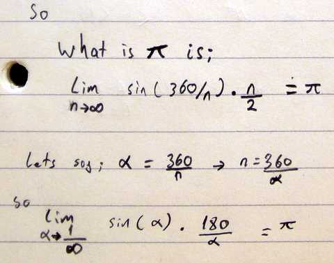
Balyoz is still in its early stage of development.I will be adding news about the progress of game.Beside, screenshots and videos will be added soon as well.
al
ates
c++

Ray Tracing on Cell by Using KD-Tree Acceleration Structure…

  • November 30, 2009
  • by hevi

It’s being a long time since promising to publish my dissertation thesis with the title of Ray Tracing on Cell by Using KD-Tree Acceleration Structure

At last I found it and decided to publish! Unfortunately html version is a bit crappy and it’s a pain in the neck to make it tidy and nice. You can also check the PDF version of my MSc thesis out.

interviews

Mind Confusing Interview Questions

  • November 16, 2009
  • by hevi

Not everyone but quite a lot of people get annoyed with frustrating interview questions, especially the ones working in gaming industry. Here are some of the questions you may also get frustrated.

1) As far as a I heard from a friend of mine this question was asked during a google phone interview;
In a virtual country all the families want to have one and only one male baby (boy) and they really insist of having that baby; they contiue giving a birth until they get the boy and they stop having baby after that.
To give an example, let sey there are only 3 families; Family A,B,C

Family A gets the boy after 4 births
G G G B

and Family B gets the boy in the first place
B

and Family C gets it after 10 tries
G G G G G G G G G B

as a result, the number of girls is 12 and boys is 3.

What would you expect the percent of the population of boys to be in this country?

The result is not that striking: 0.5

cuda

CUDA and Ray tracing; are they really a good…

  • June 29, 2009
  • by hevi

Previous week I mailed to people who worked on ray tracing with CUDA architecture and I received some disheartening mails. I would like to share these mails since you may need to understand reasons for the conflict between NVidia’s CUDA 1.1 architecture and ray tracing.

I sent this mail to “the secret matador” whom I found in NVidia’s CUDA forums;

> umut has sent you this email from
> http://forums.nvidia.com/index.php.
>
>
> Hello
> I am studying my master degree on computer games
> tech and I’m planning to choose ray tracing on cuda
> processors in dynamic scenes for my master thesis,
> however, as i read from your post itz really not a
> good idea. Is it? I am also concerned about the
> number of replies to your post (no reply as i see).
> I would like to ask you if it is a good idea to do
> my master thesis on this topic or would you like to
> suggest some different topics about CUDA?
> I would really appreciate your answer.
> Thanks
>
> UMUT
> umuter { @t } gm@il.com
>
Well, I was trying to perform raytracing with CUDA
also some time ago. My scenes contained triangles. If
you want to use CUDA for just spheres I think can be
as fast as Cell ( see
http://eric_rollins.home.mindspring.com/ray/cuda.html
)

Well, for xNormal I tryed CUDA with triangle
scenes(1-10M triangles) and I wasn’t able to get it
working at decent speed. Perhaps if you use smaller
scenes could be ok… but was terrible slow for me…
I think my scenes were too big to fit well in the
shared/const memory. I used BVHs, grids and stackless
kdtrees without any good result. A dual-core was
always faster. Btw, the CUDA stackless approach sux a
lot! CUDA is very good processing linear data(like an
image kernel) but terrible processing random and
recursive structures like the ones that requires
raytracing.

Another problem I found was that there is no CUDA x64
version, neither is Vista compatible and the VRAM on
desktop G80 cards was too small for me(256-512Mb is
the typical and my scenes were occuping almost 1Gb).
The CUDA 1.1 does not support 3D textures so is a pain
to get the uniform grids working…

Well, I hope you could improve my results… CUDA was
not very good for me. I hope they add a function
stack, better syncronization mechanism and improved
registers/instruction count for CUDA 2.

After getting this mail I asked a similar question to Eric Rollins who is most probably one of the first people trying to implement ray tracing algorithm on CUDA. And I also asked if PS3 or CUDA? which one should I choose and the answer is pretty clear; PS3. Eric Rollin’s complete answer:

Umut;

I think you are correct about the difficulties with ray tracing on CUDA. It is easier on the Cell/PS3, though still challenging. See papers linked on my PS3 ray tracing page, and MIT blue steel: http://cag.csail.mit.edu/ps3/blue-steel.shtml

In my code for CUDA and Cell/PS3 the only primitive I have implemented is the sphere.

I assume you have already seen this paper on alternative approaches: http://graphics.stanford.edu/papers/i3dkdtree/gpu-kd-i3d.pdf . Also some of the latency avoidance techniques discussed for Cell/PS3 might apply to CUDA. I do recommend reading the papers for Cell/PS3 even if you want to try CUDA.

If you have a big insight on how to do CUDA, go with it. Otherwise I recommend Cell/PS3.

Good luck.

cuda

My Masters DissertationProposal; Raytracing on CUDA

  • June 29, 2009
  • by hevi

The document below is prepared as for an MSc dissertation proposal, actual dissertation post is  here and the direct link to the dissertation pdf is here and the html version is here.

UNIVERSITY

of

ABERTAY DUNDEE

School of Computing & Creative Technologies

May 2008

By

Umut Riza ERTURK

0703851


Introduction


Introduction


High Concept

The aim of this project is to develop a real-time ray tracing system on Compute Unified Device Architecture (CUDA). The main idea is to create a generic and portable real-time ray tracer involving the realistic lightning factors such as soft shadows (penumbra), reflection and refraction with an acceptable speed of 30 frames per second (fps) for human eye by using KD-Trees on a fully parallel processing architecture; CUDA.


Project Overview

One of the most important pushing forces of the computer graphics technologies is obviously computer games which are always getting more realistic. As the games are getting developed in terms of visual realism they need more realistic visual attributes such as soft and realistic volume shadows, multi-pass lightning and complex shaders. To achieve this level realism they are not only getting more resource intensive but also getting more complicated in terms of development process with the currently most common rendering method; rasterization [03]. The main problem of this classic rendering approach is all the objects in a 3D scene are compound of triangles and all these triangles have to pass through from main processing unit to graphics processing unit one by one. In the rasterization pipeline all these triangles needs to be analyzed, coloured, lighted, textured, culled and as a result became a pixel (CDR-INF, 2007). This approach does not only give rise to a linear slow down with the increasing number of triangles in a game scene but also increases the complexity of the implementation of the effects to get a realistic result since each effect needs to be implemented with shader phases.

Despite the unrealistic results and complex implementation of the effects, rasterization considered as conventional rendering method for the computer games because of the low computation cost. However the microprocessor technology as well as the parallel-computing technologies significantly improved for the last few decades which provoked to being focused on the other alternative way for rendering; ray tracing which is a completely different technique to achieve nearly perfect visual realism. The high quality visual characteristic of ray tracing is based on the physically correct simulation of the real light behaviour. Basically ray tracing algorithm starts with sending at least one ray for each pixel from the camera to the 3D world space. If the ray intersects with an object according to the material of the object, algorithm creates the reflected-refracted rays from the object and recursively continues its process. Because of its physically correct implementation it does not struggle to create the realistic effects such as global illumination or shadowing. However this method computationally expensive due to two major problems; creating the rays and finding the intersection point of the ray and any object in the 3D space. For instance a scene with 1K triangles and with 1024×768 pixels needs at least 786432 eye rays to be created and according to the organisation method, may require millions of triangle-ray intersection tests; moreover these rays will interact with object surfaces.

With the help of the significantly improving hardware and software technologies these problems are getting easier to tackle. For the object-ray intersection problem one of the most efficient algorithms involves KD-tree structure. KD-tree is a kind of binary space partitioning (BSP) tree which is one of the most preferred data structure using for interactive scenes (Shevtsov Maxim, 2007). Briefly KD-tree is a multidimensional search tree for points in k dimensional space (NIST, 2005) which enables to find an object in the space with the complexity of log (n). In addition to this algorithmic improvement against the object-ray intersection problem, another improvement for creating rays is the parallel computing. One of the most recent parallel computing architecture is NVidia’s CUDA hardware solution whom scales up to one hundred cores and one thousand threads. Apart from the massively multi parallel advantage other advantage is its programming language which is C.

Ray tracing is one of the most promising photo realistic rendering technique for computer games according to the researches have been making on as well as according to the improvements in hardware technologies. On the other hand CUDA is a very new and promising architecture with its suitable structure for ray-tracing and there are no satisfactory researches have been done about this system. This project will investigate techniques and possible programming improvements of ray tracing on massively multi-thread architecture named CUDA.

About this Proposal Document

This proposal aims to investigate, develop and try to improve a specific real time ray tracing structure named KD-tree for a specific multi thread programming architecture called CUDA. A review of the KD-Tree structure as well as the CUDA hardware can be found in the ‘Literature Review’ section.

Following on from that research, a method for implementing the discussed techniques is presented in the ‘Method Design’ chapter. This general design is followed by a week-by-week plan detailing a schedule for implementing the proposed project, in the ‘Project Plan’ section

Literature Review

This chapter aims to summarise the certain techniques, data structures and hardwares encapsulated by the scope of this project. A brief overview of each topic is given, followed by a discussion of the key areas in each field which are applicable to this project.

Ray Tracing

Ray tracing is a rendering method to create photo realistic 2D views from 3D space by simulating the real light behaviour. It is one of the first solutions for rendering that’s why it is also one of the most researched rendering techniques up to now, however because of the complexity and amount of the calculations, mostly used for offline rendering. Contrary to its complexity the idea is very simple. Before understanding ray tracing it is essential to understand the real light behaviour since ray tracing is just a simulation of it.

What is light and colour?

Light is an electromagnetic wave in a certain range of frequency which determines the colour of the light. Apart from the wave explanation of the light the other explanation is the particle explanation; light is the compound of small packages named photons which are travelling in a certain direction with the speed of light. When a photon collides with a surface three possible scenarios happen according to the physical attributes of the surface. If the surface is reflective then the photon reflects respect o the normal of the hit point. After the reflection, photon changes its colour according to the colour of the surface. There are two kinds of reflection; ‘specular reflection’ which happens on regular surfaces and ‘diffuse reflection’ which happens on irregular surfaces.


Figure 1 – Specular Reflection of Light

Figure 2 – Diffuse Reflection of Light

Other scenario is the photon passes through the objects it is collided which is called refraction. After it enters into the object, it changes its direction according to the density of the surface and also according to the normal of the hit point.


Figure 3 – Rafraction of Light

The last scenario is it gets absorbed by the surface and neither can reflect nor refract, this happens only on real dark surfaces.

The reflection and the refraction can also happen at the same time in this case it can be considered as more than one photon has been created from one photon.


Figure 4 – Reflection and Refraction together

Basically ray tracing is the simulation of these rules in a virtual 3D world and its objective is to convert the 3D space to 2D image by determining the colour of each 2D image cell (pixel) in the 2D world. The main difference of ray tracing from the real world is, in real world all the photons are coming to our eyes from light sources directly or after reflections-refractions, however ray tracing algorithm does the reverse; sends the light rays (photons) from each of the pixels in the 2D world (screen) to the 3D world (e.g. game scene). The reason for sending rays from the screen to the scene is only the rays reaching to the screen will affect the final colour value of the pixel. That also means the photons reaching to the back face of the sphere (on Figure-5) and reflecting through an irrelevant direction will not affect the final 2D image therefore calculations for this photon are unnecessary.

Figure 5 – Basic ray tracing concept; rays from the screen to scene

Figure 6 – The dashed lines represents the wasted photons which will never reach to the screen

Figure 7 – Adaptive super sampling, sending 5 rays for each pixel for the begging, increases the number of rays if the colour difference is big between these 5 rays

Specification of the ray tracing is at least one ray needs to be sent from each pixel however in most cases one ray is not enough since the projection of one pixel may correspond to a large area in 3D world. On the other hand sending a constant number of rays (e.g. 10 rays per pixel) from each pixel, which is called supersampling, is not an efficient solution since it increases the ray tracing time linearly. Determination the number of pixels to be sent from each pixel is one of the problems of ray tracing which plays an important role on the quality issues of the image such as anti-aliasing. One of the efficient solutions for this performance-quality paradigm is adaptive supersampling. This method sends a small amount of rays from a pixel for the beginning. If the result colour values of these rays are slightly different from each other, it increases the number of rays for the current pixel and sends new rays according to the difference between rays’ colours and at the end mixes the colours of these rays to calculate the actual pixel colour (Glassner Andrew S., 1989).

After creating the rays and sending them through the 3D scene, the colliding objects with the photon needs to be found. In addition to finding the object, exact location in object space and the normal of this location needs to be found. This is one of the most challenging problems of ray-tracing and many algorithms and data structures have been discussed and implemented up to now. The most known two methods for quick finding of the hit point are bounding volume hierarchies (BVH) and KD-Trees approach. The detailed information about the KD-Trees will be discussed in the next section but BVH method will not be discussed in this paper. Although the significant algorithmic improvements about this problem, ray tracers still spend their 75% to 95% of their processing time on this problem quotes James Foley (Foley James D., 1990).

The next step after creating the primary rays and finding the intersection points is firstly looking for the hit point’s position respect to the light sources. If there is no object between the hit point and the light source then the colour of the light ray will depend on directly the light source and more other calculations.


Figure 8 – Colour of ray-a directly depends on the light source however ray-b is in shadow region since it is way to light source is blocked by itself

After taking light resources and shadows into account, next point is reflection or/and refracting the ray from the intersection point. The key input coming from the game scene to find the reflection and refraction rays is the normal of the point. A 3D scene usually compounds of geometric primitives such as spheres, cubes, planes, triangles etc. The normal calculation of a point depends on the primitive the ray intersects with. To give an example ray sphere intersection problem can easily be solved with these algebraic equations;


(Owen G. Scott, 1999)

The normal allows the reflection and refraction rays to be found;


Solution for the reflection ray Rl is;


Solution for the refraction ray Rr is;


Figure 9 – (a) reflection, (b) refraction

After finding the reflection and refraction rays the algorithms continues recursively as it is shown in the pseudo code below;


(Rademacher Paul, 2008)

Figure 10 – demostration of a ray path with reflections and refractions

As a result the image quality of this rendering technique is obviously much realistic compare to the classic rasterization method since it is a real implementation of the light behaviour. However the calculation cost for each step is still expensive to put this algorithm into current games with the current hardwares. Fortunately there are satisfactory improvements for methods as well as for hardwares. In the next section one suitable technique and a specific hardware will be introduced.

KD-Trees

KD-tree is a special kind of binary tree data structure for organising points in k-dimensional space (since the graphics applications run on three dimensional spaces the kd-tree on this paper will be representing ‘three dimensional kd-tree’) which provides multidimensional search [05]. The construction cost for the KD-tree is logarithmic respect to the number of primitives in the scene and the average cost of traversing a voxel can be estimated (Shevtsov Maxim, 2007). Another important point about kd-trees is different from octree, which divide the 3d space into constant number of parts, kd-tree divides the space into unfixed parts with planes perpendicular to one of the coordinate system axes which also differs KD-trees from the conventional BSP trees.

The use of kd-trees for ray-tracing algorithm is finding the intersecting objects in the 3D-world space with the ray sent from the camera through the scene as quick as possible.

Since there are different kinds of KD-trees according to the optimisations, roughly the data structure for a node contains two child pointers (just like binary tree), a name and a key (usually a pair of floating points) which represent the dimensions of the rectangle.

The creation of a KD-tree briefly can be described by the following steps;

  • At each step, choose one of the dimensions as a basis of dividing the rest of the point
  • For example at the root choose x-axis as the basis
    • Like binary search trees, all items to the left of root will have the x-coordinate less than that of the root
    • All items to the right of the root will have the x-coordinate greater than (or equal to) that of the root
  • Choose y as the basis for discrimination for the root’s children
  • And choose x again for the root’s grandchildren

Figure 11 – Steps for constructing a kd-tree, taken from the lecture presentations of Sharat Chandran, 2002

The major problem of constructing a kd-tree is determination of the division planes since kd-trees are not fixed divided.

As shown in figure 12, dividing a scene into two parts can be done in several ways. The problem is finding more balanced division to increase the efficiency of the kd-tree as well as the ray tracer. The optimisation is based on a simple rule; large areas with few objects or small areas with many objects work faster (Martin E., 2006).

  1. Split at the middle

  1. Split at the median


  1. Cost optimized partitioning

Figure 12 – Different division methods, taken from lecture slides of Martin Eisemann

The cost optimisation formula according to the rule mentioned above is;

Equation 1 – cost equation to split the space with higher efficiency, taken from lecture slides of Martin Eismann

As a result, the cost predictable structure of KD-trees is a very big plus for ray tracing with multi threads since the jobs can be equally distributed between threads to maximise the efficiency of the multi processing. On the other hand, KD-trees are considered as the best solution for static scenes however with the increasing interest on ray tracing algorithms, several researches have been done to use KD-trees for dynamic scenes which makes it challenging.

CUDA

For the last few years GPU devices have reached to significant computational power (figure-13) compare to CPUs. The main reason is; as the graphics operations are highly intensive and requires parallel computation, GPUs evolved in a different way from CPUs; they devotes more transistors for data processing compare to caching and data controlling (NVidia, 2007).


Figure 13 – Floating-Point Operations per Second for the CPU and GPU (figures taken from (NVidia, 2007))


Figure 14 – Difference between current GPUs and CPUs, GPUs devotes more transistors for processing (figures taken from (NVidia, 2007))

With the extremely increasing computational power of GPUs, not only graphics applications but also many other applications have been tried to be run on GPUs. CUDA has developed as hardware-software architecture to respond these needs by providing a significantly parallel and simple computation structure.


Figure 15 – Architecture of CUDA

Design goals of CUDA are described by its founder NVidia ;

  • Scale to 100’s of cores, 1000’s of parallel threads
  • Nearly auto-managed and simple parallel computing structure
  • Enabling heterogeneous systems (i.e. CPU+GPU)

Figure 16 – (NVidia, 2007)

In addition to its parallel computing power, other powerful side of CUDA is its C language which allows more understandable and clean programmes. Other important differences coming with CUDA is, contrary to other GPU programming languages such as CG or GLSL, CUDA can write arbitrary memory addresses and CUDA exposes a shared memory area of 16KB which is very fast.

Briefly, main reason for choosing this new generation hardware-software architecture is it provides great parallelisation opportunities which are very suitable for ray-tracing by using KD-trees. However CUDA’s stackless architecture is a big problem for recursive algorithms. This problem is the challenging point of the ray-tracing/CUDA combination. On the other hand recent researches showed that it is not impossible, in addition CUDA is a very new and promising system for the future applications.

Method Design

High-Level Outcomes

The aims of this project are:

  1. To implement a homogeneous (by using both the CPU as well as the GPU) real time ray-tracer on a specific system called CUDA by using a specific data structure named KD-trees.
  2. To achieve an acceptable frame rate for human eye (~20fps) and visual quality with the resolution of 800×600 in a one million-triangels scene by using a G80 GPU processor.

Programming the CPU

Constructing and updating the KD-tree data structure

According to the ray tracing algorithm there are four main processes need to be done. First process is the construction of the KD-tree according to the object locations in the scene. For a real time ray tracer not only constructing the data structure but also keeping the data structure is very important. The first major problem to tackle is using the KD-tree for dynamic scenes since its structure is more suitable for static scenes. However thankfully there are some other papers have already been published and it is proved that by using some additional data it is possible to port kd-trees to dynamic scenes (e.g. [05]). Apart from keeping the data structure updated, the 3D object data needs to be provided by the CPU to the CUDA threads.

The other three main processes (creating the rays and finding the collision point of the object and calculating the new rays reflected or refracted from the hit point) will be done by the CUDA threads.

Programming the CUDA

Ray operations

While keeping the KD-tree data structure update and sending this structure to the shared memory area of the CUDA threads, these threads will be creating the rays by using adaptive super sampling method from the screen through the scene therefore each thread will be responsible for different number of rays. This operation is not complex but heavy because of the high number of rays. The first improvement of using an extremely parallel architecture is that hundreds of these rays will be created at the same time. After creating these rays each thread will search the colliding objects in the KD-tree structure and will find the normal of the hit point according to the type of the primitive since in this project sphere and triangle primitives will be implemented. Before calculating the normals, threads will finding out if is there any direct connection between the hit point and any of the light sources. After finding if the hit point is in the shadow region or in the bright side, the colour code of this hit point will be recorded to the corresponding pixel data. Next step is finding the reflection and refraction rays. This step involves the recursion problem which is not supported by CUDA. This problem seems to be the biggest problem of the project; even though using an iterative way is not a real solution because of CUDA threads small (16KB) shared memories. To overcome with this problem there are three possible solutions; trying to limit the number of reflection and refractions (which will cause quality problems), using the global memory (which will cause performance problems) or synchronising the threads about using the shared memory (which will increase the complexity of the implementation). As a result with these reflected and refracted rays the final colour value of the pixel will be determined by using a linear blending function.

To sum up, implementation of real time ray tracing by using KD-tree data structure on CUDA architecture has many problems to overcome with. On the other hand, magnificently improving GPU technologies opens new doors to tackle these problems either by increasing its data process speed or by increasing the memory needed for these processes (i.e. it is expecting that CUDA 2.0 will involve recursion). Because of these achievements on hardware side, the interests about ray-tracing increases day by day and as a result of these achievements new methods and new scientific researches getting published every day. This project will be hopefully one of these researches.

Evaluation

Evaluation Criteria

There are two basic criteria to evaluate the result of the project:

  1. Visual quality (qualitative)
  2. Performance (quantitative)

    Qualitative

According to the project aims, the most important qualitative requirement is the visual quality of the final image. Such that, even if the visual quality of the final image is poor the speed won’t be an important since this can be easily done by reducing the number of rays sent from screen. However the quality of the image is subjective therefore the satisfaction of this criterion will be human dependent. To reduce the subjective view; one of the most common scene (named Cornell box) using in ray tracing tests will be used to test the visual quality.


Figure 17 – Cornell Box will be used for the image quality criteria

Quantitative

Since the aimed fps and the hardware as well as the software described clearly in the aims of this project, evaluating the quantitative criteria will be very basic. As soon as the getting visually satisfactory results from Cornell Box, 20 fps will be enough for the project to achieve its goal under mentioned hardware and software implementations

Project Plan

June 2008
1st – 31st Learning CUDA architecture, reviewing NVidia documents, implementation of some algorithms on CUDA to have an experience on CUDA.Revising parallel computation.
July 2008
1st – 31st Implementation of KD-tree structure, searching for improvements for KD-tree structure on dynamic scenes
August 2008
1st – 31st Constructing primitives’ data structure and working on calculation of reflected-refracted rays.
September 2008
1st w. -2nd w. Implementation of the reflection and refraction rays on CUDA
3rd w. Incorporating of super sampling method on CUDA
4th w. Progress presentation
October 2008
1st w. Preparing documentation of the progress
2nd w. – 3rd w. Integrating the CPU-side operations with CUDA-side operations. Getting first image results
4th w. Submit 1st Draft
November 2008
1st w. Maintaining of the program
2nd w. – 3rd w. – 4th w. Preparing final draft and reviewing final draft feedback.
December 2008
1st-31st Incorporate any additional changes based on final draft feedback
January 2008
Submit Dissertation

References

  • Schmittler J., Pohl D., Dahmen T., Vogelgesang C., and Slusallek P., 2005. Realtime Ray Tracing for Current and Future Games, ACM Portal, [accessed 10th May 2008], url: http://portal.acm.org/citation.cfm?id=1198555.1198762
  • Schmittler J., Pohl D., Dahmen T., Vogelgesang C., and Slusallek P., 2004, Realtime Ray Tracing of Dynamic Scenes on an FPGA Chip, ACM Portal, [accessed 10th May 2008], url: http://portal.acm.org/ft_gateway.cfm?id=1058143&type=pdf&coll=GUIDE&dl=GUIDE&CFID=68260220&CFTOKEN=96881082
  • Friedrich H., Gunther J., Dietrich A., Scherbaum M., Seidel Hans-Peter, Slusallek P., 2006, Exploring the Use of Ray Tracing for Future Games, ACM Portal, [accessed 10th May 2008], url: http://portal.acm.org/ft_gateway.cfm?id=1183323&type=pdf&coll=GUIDE&dl=GUIDE&CFID=68260623&CFTOKEN=18219301
  • Woop Sven, Schmittler Jorg, Slusallek Philipp, 2005. RPU: a programmable ray processing unit for realtime ray tracing, ACM Portal, [accessed 10th May 2008], url: http://portal.acm.org/ft_gateway.cfm?id=1073211&type=pdf&coll=GUIDE&dl=GUIDE&CFID=68261058&CFTOKEN=632516362
  • Zhou Kun, Hou Qiming, Wang Rui, Guo Baining,2008. Real-Time KD-Tree Construction on Graphics Hardware, Microsoft Research, [accessed 10th May 2008], url: ftp://ftp.research.microsoft.com/pub/tr/TR-2008-52.pdf
  • Slusallek Philipp, Shirley Peter, Mark Bill, Stoll Gordon, Wald Ingo, 2005. Introduction to real time ray tracing – course 41, ACM Portal, http://portal.acm.org/ft_gateway.cfm?id=1183323&type=pdf&coll=GUIDE&dl=GUIDE&CFID=68262552&CFTOKEN=78451416
  • Shevtsov Maxim, Soupikov Alexei, Kapustin Alexander, 2007. Highly Parallel Fast KD-tree Construction for Interactive Ray Tracing of Dynamic Scenes, Intel corporation, [accessed 10th May 2008], url: http://www.google.co.uk/url?sa=t&ct=res&cd=1&url=http%3A%2F%2Fkesen.huang.googlepages.com%2FIntel-EG07.pdf&ei=GFUsSMazL5O-0QST1JSOBQ&usg=AFQjCNHctNbBVxaKwpIZ7f71SQlBbvXobQ&sig2=iFf0gqjzcfxGAIBflFwgOg
  • NVidia, 2007. NVIDIA CUDA Programming Guide, NVidia, [accessed 10th May 2008], url: http://www.google.co.uk/url?sa=t&ct=res&cd=1&url=http%3A%2F%2Fdeveloper.download.nvidia.com%2Fcompute%2Fcuda%2F1_0%2FNVIDIA_CUDA_Programming_Guide_1.0.pdf&ei=pVYsSJGFEKa8QLXogasF&usg=AFQjCNHrbSl3bDFxVTvtHfjJ8RKpjlgxzg&sig2=Df-Ib4yBF9BFNqi_dwWAeg
  • Rademacher Paul, Ray Tracing: Graphics for the Masses, The University of North Carolina, [accessed 10th May 2008], url: http://www.cs.unc.edu/~rademach/xroads-RT/RTarticle.html
  • Glassner Andrew S., 1989. An Introduction to ray tracing, Morgan Kaufmann
  • Foley James D., Dam Andries van, Feiner Steven K., Hughes John F., 1990. Foley, James D. Computer Graphics : Principles and Practice, USA: Adisson Wesley
  • Owen G. Scott, 1999. Siggraph Education Materials(online) , [accessed 10th May 2008], url: http://www.siggraph.org/education/materials/HyperGraph/raytrace/rtinter1.htm
  • Bikker Jacco, 2005. DevMaster, Rayt`racing: Theory & Implementation Part 7, Kd-Trees and More Speed,. [accessed 10th May 2008], url: http://www.devmaster.net/articles/raytracing_series/part7.php
  • Chandran Sharat, 2002. University of Maryland web site Data Structures lecture notes, Introduction to kd-trees, [accessed 10th May 2008], url: http://www.cs.umd.edu/class/spring2002/cmsc420-0401/pbasic.pdf
  • Martin Eisemann, 2006. University of Carolo-Wilhelmina, Computer Graphics- kD-Tree and Optimizations for Ray Tracing, [accessed 10th May 2008], url: http://graphics.tu-bs.de/teaching/lectures/ws0607/CG1/slides/07-kD-Tree.pdf
  • Marlon John, LaMothe Andre, 2003.
    Focus on Photon Mapping, Ohio:Premier Press.
  • CDR-INF, 2007. Real Time Ray-Tracing May Replace GPU Rasterization, [accessed 10th May 2008], url:
    http://www.cdrinfo.com/Sections/News/Details.aspx?NewsId=21608
  • NIST (National Institute of Standards and Technology), 2005. K-D tree data structure, [accessed 10th May 2008], url:
    http://www.nist.gov/dads/HTML/kdtree.html
artificial intelligence

Short Term Decision Making with Fuzzy Logic And Long…

  • June 24, 2009
  • by hevi

Abstract

Real-time strategy is one of the most important game genre from the beginning of the computer games history and one of the biggest inner market in computer games market, in spite of that fact there are only a few strategy games have successful AIs. This paper will try to improve real-time strategy games’ AI by improving long term decisions such as; resource management, determining correct buildings to build, achieving correct upgrades/technologies with neural networks as well as to short term decisions such as; creating correct troops against opponents’ troops, determination of attacking or fleeing, attacking to correct enemy troops. Also this paper will try to give examples from strategy games such as Command and Conquer: Tiberium Wars, Age of Empires.

Key Words: Artificial intelligence in real-time strategy games, fuzzy logic, neural networks, short term decision making in strategy games, long term decision making in strategy games.

1.     Definition of Fuzzy Logic

The best definition of fuzzy logic is given by its inventor Lotfi Zadeh; “Fuzzy logic means of representing problems to computers in a way akin to the way human solve them and the essence of fuzzy logic is that everything is a matter of degree.”

The meaning of solving problems with computers akin to the way human solve can easily be explained with a simple example from a basketball game; if a player wants to guard another player firstly he should consider how tall he is and how his playing skills are. Simply if the player that he wants to guard is tall and plays very slow relative to him then he will use his instinct to determine to consider if he should guard that player as there is an uncertainty for him. In this example the important point is the properties are relative to the player and there is a degree for the height and playing skill for the rival player. Fuzzy logic provides a deterministic way for this uncertain situation.

There are some steps to process the fuzzy logic (Figure-1). These steps are; firstly fuzzification where crisp inputs get converted to fuzzy inputs secondly these inputs get processed with fuzzy rules to create fuzzy output and lastly defuzzification which results with degree of result as in fuzzy logic there can be more than one result with different degrees.

image004

Figure 1 – Fuzzy Process Steps (David M. Bourg P.192)

To exemplify the fuzzy procee steps, the previous basketball game situation could be used. As mentioned in the example the rival player is tall with 1.87 meters which is quite tall relative to our player and can dripple with 3 m/s which is slow relative to our player. Addition to these data some rules are needed to consider which are called fuzzy rules such as;

  • if player is short but not  fast then guard,
  • if player is fast but not short then don’t guard
  • If player is tall then don’t guard
  • If player is average tall and average fast guard
image005

Figure 2 – how tall

image007

Figure 3- how fast

According to the rules and the input data an output will be created by fuzzy system such as; the degree for guard is 0.7, degree for sometimes guard is 0.4 and never guard is 0.2.

image009

Figure 4-output fuzzy sets

On the last step, defuzzication, is using for creating a crisp output which is a number which may determine the energy that we should use to guard the player during game. The centre of mass is a common method to create the output. On this phase the weights to calculate the mean point is totally depends on the implementation. On this application it is considered to give high weight to guard or not guard but low weight given to sometimes guard.  (David M. Bourg, 2004)

image012

Figure 5- fuzzy output (David M. Bourg P.204)

Output = [0.7 * (-10) + 0.4 * 1 + 0.2 * 10] / (0.7 + 0.4 + 0.2) ≈ -3.5

As a result fuzzy logic is using under uncertainty to make a decision and to find out the degree of decision. The problem of fuzzy logic is as the number of inputs increase the number of rules increase exponential.

2.     Definition of Artificial Neural Networks

Although there is no agreed definition the most common definition is “it involves a network of simple processing elements (neurons), which can exhibit complex global behaviour, determined by the connections between the processing elements and element parameters” (Wikipedia, Artificial neural network).

The structure of ANN (Artificial Neural Networks) is same with human’s neural network’s structure as in human neural system there are receptors to collect the data named dendrites, a processing unit named cell body and an output unit named axon. Similar to this structure in ANN there is an input layer, a processing unit which sums the inputs after multiplying them with weights and an output layer which gives a result for a neuron (Figure 6).

image014

Figure 6- structure of a simple neuron (Mat Buckland, 2002, p.241)

As seen in the figure the output will depend on the inputs and the weights as well. This is the main point of the ANN as if we can find the correct weights for the inputs than we can create a correct result for ever situation. On reverse order if we know  have the inputs and if we know the results for every input pair than we can calculate the weights therefore after finding weights if we give input values to our neural network it can calculate the correct output for certain input pairs. This method which is called back propagation is a supervised learning. The problems of that method are; training sets for feeding the ANN may not have all the possibilities or these sets may contain novel data (Dr Emma Hart, 2005).

Although the logic sounds pretty easy for ANNs with supervised learning, there is a mathematical background which makes this logic work for computers. On this part of this paper no mathematical background will be explained since it is not the main goal of this paper. (To get more information about ANNs please check further reading)

image016

Figure 7- structure of a neural network with one input layer, one hidden layer and one output layer (Mat Buckland, 2002, p.242)

As seen in the figure above there is a hidden layer which is necessary to make complex calculations. A neural network without hidden layer can make logical calculations such as ‘AND’ and ‘OR’ but cannot calculate XOR operation. This means that for complex calculations the hidden layer is obviously necessary. The number of neurons in the hidden layer is up to implementation. Increasing number of hidden layers increases the precision and complexity of the calculations which results with accurate calculations with using more CPU time and more memory that is the trade off. To find the best number of hidden layers the only way is experimenting different values, however, there are different estimations for that problem such as square root of number of input layers multiply by number of output layer.

In brief, ANNs are using for complicated or imprecise data and also for recognising the patterns (Christos Stergiou, NEURAL NETWORKS). Recognition of patterns requires very complicated methods and data structures with classic methods; however ANNs are very simple structures which make the implementation easier as ANNs are self-organising structures as well. The cons of ANNs with back propagation supervised learning are; high consumption of resources, choosing correct propagation sets, choosing correct number of hidden layers and hard debugging.

3.     Real Time Strategy Games (RTS Games)

A RTS game is a strategic game which runs in real time distinguish it from turn based strategy games. Although the high number of RTS games there are only a few scenarios are used for these games. The most popular scenario starts with a couple of productive units such as villagers, and a few resources. The player should use the villagers to collect resources and create new buildings or units who can be soldiers or villagers. The buildings usually enable new unit tapes. To give an example the player can create knights by using stable and to build a stable a barracks should have been built. On the other hand to upgrade the unit strength usually players should achieve new technologies which are usually much costly than unit production. As seen in this scenario usually in RTS games there is a hierarchical order which the player should follow to defeat the enemy.

Although there is a static hierarchical order for creation of units or achievement of technologies, always complex algorithms running for RTS games AI since the number of probabilities and parameters are very high for making decisions. Moreover the only problem in RTS games is not decision making but also path finding or this kind of AI algorithms but in this paper only decision making will be discussed.

In the history of RTS games, game AIs usually statically programmed like finite state machines for decision making. To give an example AOE-2 (Age of Empires II) has a rule based AI with priority queues which means nearly static development for NPC (non player character). If the player can find a way to defeat the NPC than the player will never lose again as the NPC cannot evolve itself and cannot find a way to overcome the bottlenecks of its management strategy. Besides these long term decision failures in AOE-2 consideration mechanism for choosing the correct the enemy to attack is not working at all as the troops always choose and attack an enemy until they die. This makes the game AI dummy since if the human player creates a trap with a wall such as builds a wall around an archer, all the knights try to attack this archer but they are not able to attack because of the wall but they lose lots of energy or time. Even if the AI programmer can find out this bug and tries to prevent this situation, he has to write lots of scripts as there is no rule to generalise in this situation. That makes the AI very complicated.

Thankfully in new generation games such as Command Conqueror Tiberium Wars, the troops behave reasonable as they can choose the correct troop to attack according to its health. To give an example all the troops choose the enemy with lowest health in their range but this approach still involves some problems. Moreover this game has obviously problem while making long term decisions because NPC obviously cheats by having lots of recourses and by producing them very fast. These approaches make strategy games very boring for game players as if the game player can defeat NPC for once then computer nearly has no chance to win again. That’s because of their static structure and behaviours.

To find alternative solutions for these problems in this paper the decisions will be divided into two parts according to their importance. If the decision is unit wise such as choosing the correct troop in the range to attack will be called as short term decision. On the other hand the decisions, like choosing correct technologies to achieve, which are not individual decision for a troop but about a certain group of all troops in the game or the decisions which will affect the destiny of the game for long term will be called long term decisions.

Not only the importance but also the complexity of the decisions is another reason for this differentiation. The short term decisions such as considering the correct troop to build is a less complex decision compare to resource management and it is only uncertain which means can be found out by analysing some other parameters.  However the resource management cannot be done by analysing some parameters because of the huge amount of the parameters and complex relations between these parameters.

a.      Short Term Decisions in Real Time Strategy Games

As mentioned before, short term decision means instantaneous decisions made by individual troops or the controlling mechanism such as; decision of attacking or fleeing or creating the correct troops according to immediate data. Although these kind of short term decisions are unpredictable, they can be made by deterministic calculations such as Fuzzy Logic which provides a high resolution for output with crisp input data. In the next parts of this paper, these short term decisions will be discussed in terms of their input data, output data and the way to make these decisions with the explanations.

The sections below based on a hypothetical RTS game scenario. In this hypothetical RTS game the units have the properties showed on the list below with explanations.

Health The health of the troop, in fuzzy set it will be normalized range between [0,100], 100 represents the healthiest and 0 is death.
Armour Unlike some of the RTS games, in this example there is only one type of armour for the troop which reduces the attack power of enemy against the troop.
Attack Power Attack power of troop against the enemy.
Attack Speed Attack speed is the variable defines how many time can the troop attack to the enemy in a constant time interval
Movement Speed Differs from attack speed, this is the parameter to define how fast the troop move or escape, it is constant for every type of the troops.

And the parameters are found by some calculations using the variable above. The main reason for doing that is having more realistic information. To give an example, let’s assume there is two kinds of troops first one with attack power of 50 and attack speed of 1, the other troop has the attack power of 15 with the speed of 4. This means that while the first troop causes 50×1 = 50 units of damage in T seconds but the second troop causes 15×4 = 60 units of damage which means the second troop is stronger than second one.

Relative Attack Power image017 OAS = Own Attack Speed

EAS = Enemy’s Attack Speed

image019= Sum of the powers of the troops attacking to the target troop

image021= The target troop’s armour

image023= Sum of the powers of the enemy troops attacking to the troop

image021= Enemy troop’s armour in the aim of the troop

image025= The troop’s Armour.

This variable normalized by multiplying with 50. The result of 50 means equality.

Relative Speed image027 image029= Own Movement Speed

image031= Enemy’s Movement Speed

image033= The mean of the speeds of the attacking troop’s to the target troop.

image035= The mean of the speeds of the enemy troops attacking to the troop.

This variable normalized by multiplying with 50. The result of 50 means equality.

The usage of  symbol adds the group behaviour for the decision making. To give an example, if the Team A has only one troop with good condition in terms of its health, on the other side Team B has five troops and all of them heavily injured but has the opportunity to destroy the enemy troop. On this condition if the consideration algorithm runs on only the troops one by one than all the Team B troops should escape from the clash but actually they shouldn’t since they can destroy the enemy.

Another example for better understanding can be given from the figure below. The troop with number 7 from the Square Team is attacking to the troop with number 2 from the Circle Team and the number 2 is being attacked by number 8 as well. On the other hand number 7 is being attacked by number 3. On this condition RAP (Relative Attack Power) of number 7 will be calculated by sum of powers of number 7 and number 8 divide by the attacking power of number 3. So the equation for RAP is;

image039

Equation 1 – RAP Equation for Troop 7

image041

Figure 8 – A clash example between two forces

i.      Attack or Flee

In a RTS game one of the most usual decisions to be made is the individual decision of a troop to continue attacking or start fleeing. In most of the RTS games like; warcraft, dune 2000, command conqueror as well as age of empires these kinds of decisions made by FSM (finite state machines). The main reason for these games to use finite state machines can be predict as reducing the CPU time for game AI as FSM is a static structure which needs minimum amount of resources but the problem of this structure is the number of states and unrealistic behaviour.

Apart from FSMs another approach can be the Fuzzy logic which provides realistic behaviour but consumes more CPU time but this is a trade off and acceptable due to the increasing CPU/GPU power.

The first stage to setup the fuzzy logic is determination of Fuzzy Input data Sets (FIS) and membership functions. However it’s better to define the Fuzzy Output Set (FOS) and its membership functions as we have only two FOSs; first one is Attack, second one is Flee (figure-9).

image044

Figure 9 – Fuzzy output sets and member functions

The FISs are Own Health, Enemy’s Health, Relative Attack Power (RAP), Relative Movement Speed (RMS). With the help of these variables the troop will show the group behaviour and make realistic decisions.

The other step is determination of membership function. On this paper only linear membership functions such as triangle and trapezoid used for easy understanding as well as easier calculation, however it is better to use logarithmic curves for RAP and RMS since they are the results of division of two forces and two speeds. For both of these data sets 50 represents the Equality.

Own Health

Enemy’s Health

RAP

RMS

Near dead

Near dead

Weak

Slow

Injured

Injured

Equal

Equal

Normal

Normal

Strong

Fast

Table 1 – Fuzzy Input Sets

And the third step is defining these FIS’s membership functions.

image046

Figure 10 – Membership function for Own Health / Enemy’s Health which are normalized to 100

The figure above shows the membership function for Own Health as well as Enemy’s Health. As seen in figure, the health under 10 is definitely named like near dead and over 30 counts like Normal. The main reason for doing that is to prevent all the troops escape from the battle as all the troops should definitely fight if they are over 30 and they should try to escape if they are near dead.

The figure below shows the RAP membership function. In this MF (membership function), equality is 50 and definitely stronger means 1.2 times stronger than the troop which is equal to 60 and definitely weaker means 1.2 time weaker than the troop which is equal to 46.6.

image048

Figure 11 – RAP Membership function

image050

Figure 12 – RMS Membership function

On the other hand 1.1 times faster means definitely faster and 1.1 times slower means definitely slower. The tolerance is 10% to prevent the errors. If the tolerance is kept 20% than the flee consideration may not work as fifteen percent slower means no way to escape so it is better to keep the tolerance at 10%.

And the last part is determination of rules. This part is the most important and most open part to make mistakes. In addition, the numbers of all combinations are. However it is not necessary to create all the rules for every possibility. In our system the rules are; 3x3x3x3=81

INPUTS

OUTPUT

Own Health

Enemy’s Health

RAP

RMS

Attack / Flee

Not near dead

All possibilities

All possibilities

All possibilities

Attack

near dead

All possibilities

All possibilities

Slower

Attack

near dead

injured

equal

Not faster

Attack

near dead

near dead

Weaker

Not slower

Flee

near dead

injured

Weaker

Not slower

Flee

near dead

normal

Weaker

Not slower

Flee

near dead

normal

equal

faster

Flee

near dead

normal

stronger

faster

Flee

near dead

injured

equal

faster

Flee

Table 2 – Fuzzy Conditions for Attack or Flee

If the troop is not heavily injured (not near dead) then it should continue attacking and shouldn’t escape. The problem is if it is near dead since all the flee possibilities needs this condition first. But even if the troop is near dead and slower than the enemy it should attack because there is no way to escape and the rest of the rules are easy to understand with the help of the table above.

And the very last part is testing the fuzzy system with different data. All the data should start with the near dead condition or injured for Own Health since for the condition of normal, troop will definitely attack.

One of the best examples is giving these values;

Own Health

Enemy’s Health

RAP

RMS

Result

9.38(near dead)

35.6(normal)

56.8(stronger)

53.1(faster)

Attack

9.38(near dead)

36.9(normal)

56.8(stronger)

53.1(faster)

Flee

8.38(near dead)

35.6(normal)

56.8(stronger)

53.1(faster)

Flee

Table 3 – Test decisions

Although the only difference is enemy’s health with the difference of 1.3 the result changes and seems to be a good decision since if the enemy is weaker than there is a possibility to kill because it is stronger. And the next turn if the troop got closer to death than will definitely escape showed at the last line of the table above.

image054

Figure 13 – Decision is attack with the value of 51.1

image056

Figure 14 –  Decision is flee with the value of 49.6

ii.      Choosing Correct Troop to Attack

Another short term decision for individual troops in the RTS games is choosing correct troop to attack. This decision also is a short term decision since it is only related with an individual troop also in this part of this essay; Fuzzy Logic will be used to answer this question. The main reason for using Fuzzy Logic is the problem involves uncertainty and the solution should be deterministic. To give an example during a clash between two enemy groups let’s assume that Team 1 has one troop and Team 2 has two troops and the troop in team 1 trying to determine which enemy troop to attack also let’s assume that for each troop number of properties are three such as; health attack, power as well as armour. In this situation this troop should choose it according to degree of weakness of the enemy and this weakness should be calculated with the help of these troops’ properties. This explanation seems best fit to Fuzzy Logic to be used for determination.

The FIS terms and the explanations for the hypothetical game scenario of this section are;

Own Effective Attack Power (OEAP)

image057

OAP = Own Attack Power

OAS = Own Attack Speed

EAR = Enemy’s Armour

EFH = Enemy’s Full Health

Enemy’s Effective Attack Power (EEAP)

image059

EAP = Enemy’s Attack Power

EAS = Enemy’s Attack Speed

OAR = Own Armour

OFH = Own Full Health

Enemy’s Health (EH)

image061

ECH = Enemy’s Current Health

EFH = Enemy’s Full Health

This variable normalized between [0-100] where 100 is healthiest.

These equations differ from the equations in `Attack or Flee` section of this essay since while determining the correct troop to attack should be done according to individual attack power not group attack power. The main reason for doing that is, if the group power is calculated instead of individual power against an enemy troop we cannot really choose a weak enemy for our attacking skills.

Another interesting point for this approach is this part doesn’t include Own Health parameter since this section is not determining our attacking or fleeing decision this means that the decision of the troop should be best fitting decision for the weakness degree not our own health.

After choosing FISs second part is creating the MF for these FISs.

image064

image066

image068

Figure 15 – Membership functions for Choosing Correct Troop to Attack

Different from the ‘Attack or Flee’ section, there are four MFs where healthy MF is new. The mean reason of putting the healthy parameter is increasing the precise for enemy’s health MF since it is really important for the decision calculation.

The next step for creating our fuzzy logic is creating the output (FOS). The output membership graph consists of three possibilities as we need a precise output for this short term decision.

image070

And the third step is creating rules. In this section, there are 36 possible combinations however it is reduced by using not operations as a result there are 15 combinations to implement, these are;

Inputs

Output

OEAP

EH

EEAP

strong not healthy All conditions attack
strong healthy All conditions neutral
not weak near dead not weak attack
weak near dead weak neutral
not weak injured All conditions attack
weak injured All conditions attack
normal healthy All conditions neutral
weak healthy All conditions don’t attack
normal normal strong attack
normal normal not strong neutral
weak normal All conditions don’t attack
weak not near dead All conditions neutral
not weak All conditions strong attack
weak All conditions strong neutral

Table 4- Fuzzy rules for choosing correct troop to attack

The main goal of these rules is attacking to the weakest in terms of its health and our attack power against this troop as well as the strongest enemy in terms of its attack power. After creating out fuzzy system the troop can choose the weakest enemy after the defuzzication operation.

image071

Figure 16- Example for which troop to attack decision

To give an example, let’s suppose that there are three troops, first and second are from Circle Team and the third one is from Square Team (Figure 16). And the variables for the troop 3 against 2 and one are;

Troop 1

Troop 2

OEAP

EH

EEAP

OEAP

EH

EEAP

88

19

88

55

7

95

Under these conditions, the troop is powerful against the troop 1 and health of troop 1 is bad but better than troop 2, however, troops 2’s effective attack power is better than troop 1. So it is hard to determine since troop 2 is closer to dead but our attack power is not as strong as against troop1. But the fuzzy logic has an answer for both of the troops;

Troop 1

Troop 2

Output (result of defuzzication)

66.7

67

Also the results of the fuzzy logic are very close to each other as expected but there is a numerical result that we can decide according to. So the troop will attack to troop 2 as the output is bigger than troop 1’s output.

image074

Figure 17- Outputs for troop 1

image076

Figure 18- Outputs for troop 2

b.     Long Term Decisions in RTS Games

The easiest explanation for long term decisions in RTS games can be described as the decisions which affect all or a group of troops or buildings for a long time as well as can be considered as the management strategy of the game player. The best example for long term decisions is resource management during game play which means how many resource collectors (e.g. villagers, harvesters) should be created and ordered to collect certain types of resources. In addition to resource managements other examples for long term decisions are; determining correct buildings to build, achieving correct upgrades/technologies, choosing correct time to attack with full power etc.

Not only for RTS games but also for any kind of game long term decision making always a big problem as the number of possibilities is may not be a certain value. Even if the numbers of possibilities are certain then possibilities and parameters are too much to make an easy decision. Moreover the difference between a short term decision and a long term decision is simply unreasonable short term decisions can be fixed in a short time however long term decision cannot be fixed so easily.

For RTS games long term decisions are vital since the CCP (computer controlled player) should behave realistic, intelligent as well as shouldn’t to not to frustrate the human player. The most common method for making these kinds of decisions are again the finite state machines which cause nearly a static game play. Every time the game player experiences the same game for the same map. To give an example in AOE2, at the end of the fourth minute, the CCP sends a scout to explore the map and creates a static number of villagers, orders them in a static way such as; four villagers hunt deer, ten of them collect food from trees etc., at the end of the seventh minute CCP attacks with a constant number of troops. This causes very static game scenario since the human player finds a way to repel the CCP and after the human player cannot be defeated by the CCP because the CCP cannot create any new way. The game producers of these RTS games usually create an AI with a static behaviour by using scripting languages. Therefore to create a strong opponent against the human player they prefer using cheating methods such as gifting new troops as well as resources which frustrates the human player.

To create a realistic behaviour for CCPs, which means intelligent and learnable behaviour, some other methods should be used such as ANN since it provides learning for CCPs. In addition to this ability of ANNs, ANNs may also provide un-deterministic behaviour by integrating GA (Genetic Algorithm). However, this method consumes lots of CPU time and provides a very slow learning.

This section of this paper will recommend using ANN (artificial neural networks) for long term decision making by giving some basic ideas such as defining input layer parameters for ANN and the outputs as well. However, all the recommendations are hypothetical since none of the ideas are based on any calculations or experiment. For these hypothetical recommendations the famous RTS game AOE2 (Age of Empires 2) will be used as the RTS game environment.

i.      ANN Structure and Hypothetic Feeding Mechanism of the ANN

As mentioned before on this paper, an ANN structure consists of three fundamental elements; inputs, weights and outputs. In our system inputs are the numerical values of a relevant system such as; for resource management system first input can be the recourse (e.g. gold, wood) the player has and the outputs are actions such as; create villager or send a villager to collect gold.

image077

Figure 19 – An ANN Module

As mentioned before, the training method for the RTS AI is back propagation which is a supervised learning method and the weight calculations are not dynamic. This means the calculation of weights can be done after the game play.

To reduce the calculations and to separate behaviours, the module approach is preferred to be used.  To give an example from our conceptual game AOE2, behaviour of the CCP during dark-age in terms of resource collection should be different from castle age. Instead of using the current age as an input value for the AI, creating different ANN modules can be another approach. This also provides parallel calculations for server-side such as calculation of dark- age could be made separately from the calculation of castle age by using threads. Another benefit of this approach is the success of each module can be send to server as training data if it fits the necessary criteria such if the player achieves castle age before computer this data can be send to the server even if the player losses the game. However, determination of the criteria should be search carefully to not to train the AI with novel data.

image079

Figure 20 – Before games start all weights getting from AI server

To load the weights of the game AI, the client should connect to the AI server and should get the trained ANNs weights to provide a better and dynamic game play. This method can be another approach for reducing piracy in games like, if the player uses a pirate version of the game cannot download the last AI weights since to download the AI data server can request for the player ID and password first.

Also the game AI server should contain trained and tested data before release of the game AI since, no one wants to play with a dummy AI. So the game company should be well trained the game AI modules which can be a problem for the game development.

image081

Figure 21 – At the end of each game all input and outputs sending to AI server for calculation of weights if the result of the game is successful

Briefly the steps of this system are;

For AI loading;

  1. Connect to AI server
    1. Check for ID, Password
    2. Send weights if successfully connected
    3. Create the local AI with new weights
    4. If cannot connect
      1. Use the previous ANN weights.

For data collection (collecting the training data);

  1. For every action
    1. Collect input variables of the relevant AI module
    2. Collect the action
    3. If the current ANN module reaches the criteria to be changed
      1. Change the ANN module
      2. If the ANN training data reaches the criteria, mark to be sent to server
      3. Else don’t mark and don’t discard the ANN training data set
      4. At the end of the game
        1. Send all ANN training data sets of the winner’s.
        2. Send all the marked ANN training data sets.

For Server Side Weight calculations;

  1. If there is new data,
    1. join all the data of relevant ANN modules including new data and old data
      1. i.      Create threads for every ANN module
      2. ii.      Calculate until reaching a threshold for every ANN module
      3. If there is no new data,
        1. Define threshold values lower than the old threshold values
          1. i.      Create threads for every ANN module
          2. ii.      Calculate until reaching a threshold for every ANN module

ii.      Example ANN Structure – 1: Resource Management in Dark Age

To create the ANN structure first of all the input values should be determined. In a RTS game for resource management can be the number of resources, number of troops collecting the resources.

For our example game AOE2, the input values for dark-age can be chosen like;

1. Number of workers

2. Number of workers collecting food

3. Number of workers collecting wood

4. Number of workers collecting gold

5. Number of workers collecting stone

6. Amount of wood we have

7. Amount of wood we have

8. Amount of gold we have

9. Amount of stone we have

10. Race of the side (such as Aztecs, Goths, Turks etc.)

And the outputs of the ANN module are decisions such as;

1. Create villager

2. Send a villager from food to wood

3. Send a villager from food to gold

4. Send a villager from food to stone

5. Send a villager from wood to food

6. Send a villager from wood to gold

7. Send a villager from wood to stone

8. Send a villager from gold to food

9. Send a villager from gold to wood

10. Send a villager from gold to stone

11. Send a villager from stone to food

12. Send a villager from stone to wood

13. Send a villager from stone to gold

The data collection in the game should be triggered by the action such as, if the player choose a villager from stone collection and send him to wood collection than all the input data and should be collected after the worker starts working.

At the same time another module is working for achieving technologies and if the resources are enough to pass the next age than all the data should be recorded according to the algorithm mentioned before.

iii.      Example ANN Structure – 2: Deciding the Correct Troops to Create

This part can be a either fuzzy logic or ANN since it seems like a spontaneous action, however the number of variable makes the fuzzy logic nearly impossible to implement this part and also actually this decision is not only spontaneous but also effects the game in long term as creating of Paladin is as expensive as achieving some technologies.

The input variables can be;

  1. Number of own archers
  2. Number of own knights
  3. Number of own swordsmen
  4. Number of own skirmishers
  5. Number of own special troops
  6. Number of own other troops
  7. Number of own defensive buildings
  8. Number of enemy’s archers
  9. Number of enemy’s knights

10.  Number of enemy’s swordsmen

11.  Number of enemy’s skirmishers

12.  Number of enemy’s special troops

13.  Number of enemy’s other troops

14.  Number of enemy’s defensive buildings

15.  Score of the enemy (this variable provided by the AOE2 game environment)

16.  Own score

17.  Own race

18.  Enemy’s race

19.  Amount of wood we have

20.  Amount of wood we have

21.  Amount of gold we have

22.  Amount of stone we have

Outputs are decisions again;

  1. Create archer
  2. Create knight
  3. Create swordsman
  4. Create skirmisher
  5. Create special troop

As seen above, the numbers of inputs are pretty much since it is really hard to determine even for human instinct which troop to create that makes the game interesting and keeps players’ passions on the game. Therefore if this system really can be implemented and reaches a degree of success than game’s lifetime for players definitely will be longer as most of the strategy game players play strategy games for the game AI not only for graphics.

Conclusion

Artificial intelligence is the most important for strategy games and especially for real time strategy games since the computer controlled opponents should make reasonable decisions spontaneously. For most of the strategy games, game producers preferred the easy way; cheating in different ways such as giving new troops, increasing income rate providing from resources and other similar ways, however results of these methods never satisfied the game players. The most important reason for that is; when the human player finds a way to defeat the computer, by using the same patterns (tactics), the human player never lose again. Briefly human player can learn but the computer cannot. Actually they can but this method never tried in commercial strategy games. There are several reasons behind that; first of all the CPU intensity of the learning structure, secondly the success rate is not known as the learning method hardly used in games. Not only machine learning but also spontaneous decision making, in most of the strategy games, is poor. Actually these short term decisions can be made with fuzzy logic and in some of the new strategy games it seems to be used (Command Conqueror Tiberium Wars) for choosing correct troop to attack, however it is not definite since no explanation have been made about the game AI for this game.

At first sight the implementation of fuzzy logic could be seem like simple especially for the short term decision making, however, the exponentially increasing number of possibilities makes hard the fuzzy logic to be implemented. On the other hand, in this paper, the tested short term decisions seem working. Especially choosing correct troop in the range to attack seems to be a successful application of fuzzy logic according to test results but without a real time application it is not reasonable to judge as a successful application of fuzzy logic since CPU usage is not known.

The conceptual distributed server based ANN application hasn’t tried yet by any game. Besides this kind of distributed approach haven’t tried for any kind of game AI yet. The CPU usage problem of the ANN is a known weak point of this structure. Another weak point of ANNs is the requirement for huge number of feed data (training). This conceptual distributed system may be a key for solution of these problems. Additionally, this trained AI structures can have a commercial value since they can decrease the number of pirate usage as the strategy game players always want to play with a more intelligent opponent and most of them will want to be registered to the AI service provider this means preventing piracy.

As a result, the problems about short term decision making and also long term decision making tried to be solved by using ANNs and Fuzzy Logic but none of the approaches has been tried in a real time game. However, the results for fuzzy logic seem to fit like a glove the given problem. On the other hand the conceptual ANN distributed system can be a new approach for solving the problems of ANNs in RTS games.

References

[1] David M. Bourg & Glen Seemann, AI for Game Developers, July 2004, First Edition, O’Reilly

[2] Mat Buckland & Andre LaMothe, AI Techniques for Game Programming, 2002, Premier Press

[3] Mat Buckland, Programming Game AI by Example, 2005, Wordware Publishing Inc.

[4] Todd Barron, Strategy Game Programming with DirectX 9.0, 2003, Wordware Publishing Inc.

[5] Mark A. DeLoura (edited by),  Game Programming Gems, 2000, Charles River Media

[6] Mark A. DeLoura (edited by),  Game Programming Gems 2, 2001, Charles River Media

[7] Steve Rabin (edited by), AI Game Programming Wisdom, 2002, Charles River Media

[8] T.J.A. Jansen, Player Adaptive Cooperative Arti_cial Intelligence for RTS Games, June 13, 2007, http://www.cs.unimaas.nl/~uiterwyk/Theses/BSc/Jansen_BSc-paper.pdf, last visit date: 30-11-2007

[9] Michael Chung, Michael Buro, and Jonathan Schaeffer, Monte Carlo Planning in RTS Games, http://www.cs.ualberta.ca/~mburo/ps/mcplan.pdf, visit date: 30-11-2007

[10] F.C. Schadd, June 13 2007, Hierarchical Opponent Models for Real-Time Strategy Games http://www.cs.unimaas.nl/~uiterwyk/Theses/BSc/Schadd_BSc-paper.pdf, visit date: 30-11-2007

[11] Daniel Johnson and Janet Wiles, Computer Games with Intelligence, http://www.itee.uq.edu.au/~uqdjohns/publications/AI/AJIIPS_AI.pdf, visit date: 30-11-2007

[12] Wikipedia, Artificial_neural_network, http://en.wikipedia.org/wiki/Artificial_neural_network, last visit date: 30-11-2007

[13] Wikipedia, Fuzzy Logic, http://en.wikipedia.org/wiki/Fuzzy_logic, last visit date: 30-11-2007

[14] Dr Emma Hart, Lecture Notes; Introduction to Neural Networks, 13-04-2005,  http://www.soc.napier.ac.uk/module.php3?op=getlecture&cloaking=no&lectureid=365774, last visit date: 30-11-2007

[15] Christos Stergiou and Dimitrios Siganos, NEURAL NETWORKS, http://www.doc.ic.ac.uk/~nd/surprise_96/journal/vol4/cs11/report.html#Why%20use%20neural%20networks, last visit date: 30-11-2007

[16] Stuart James Kelly, Applying Artificial Intelligence, Search Algorithms and Neural Networks to Games, 2003, http://www.generation5.org/content/2003/KellyMiniPaper.asp, last visit date: 30-11-2007

[17] Artificial Neural Networks, 1999,  http://www.psych.utoronto.ca/users/reingold/courses/ai/nn.html, last visit date: 30-11-2007

[18] Artificial Intelligence in Games , 17 Jul 2006, http://www.codeproject.com/KB/architecture/aigame.aspx, last visit date: 30-11-2007

c++

Reinventing the wheel : write your own fast sine…

  • June 24, 2009
  • by hevi

A couple of days ago I tried to self study the mathematical explanation of pi (π) and ended up with very interesting results and ideas 🙂

First of all lets answer the classic question; What is pi?

Pi or π is a mathematical constant whose value is the ratio of any circle‘s circumference to its diameter in Euclidean space… (Wiki)

From its definition it is pretty easy to find it depending on another mathematical function: sinus.

I can hear that two questions rising up in minds rapidly;

1) Why would I need that? -I don’t know the answer, just curiosity 🙂

2) How? – Answer is in the rest of the post… continue… cmon, go on!

Since it is hard to write mathematical formulas and drawing shapes on our stupid HCI (human computer interaction; keyboard, mouse, etc.) slavery, I prefered to write them on a notebook and took their shots for the ease of understanding and publishing.

Relation Between Pi and Sinus Function

At first galance it is necessery to know that a circle can be expressed by infinite number of triangles,
so let’s start with the most basic equilateral; square.


The first half of the image above shows how to find the area of the square by using its half-diagonal which is the first step to do inductive reasoning.
And the second half is a generalisation of the formula for an equilateral with ‘n’ sides/corners.

As much as we increase the number of sides of the equilateral as much as it approximates to a circle,
Let’s think that we have an equilateral with infinite sides, then it turns into a circle which means in the result formula if we give a very big value to ‘n’ and 1 to ‘r’, then the result approximates to pi.

instead of depending on the number of sides in the equilateral, we want to be dependent to the angle alpha, to do that we simply replace n with 360/alpha.

the conclusion of this part is awesome; we can find the value of sinus in the degree range of zero and ten, with an acceptable error (+0.001) by only one multiplication.

Some Trigonometry

Althoug it is possible to achieve relatively accurate results with the formula shown above for angles between 0 and 10, as the angle gets wider as it loses its accuricy. Therefore we have to use the magic formula for angles less than 10 but how?!

The answer comes from the trigonometric sine addition formula;

sin(a+b) = sin(a) cos(b) + sin(b) cos(a)

If we can keep the ‘b’ less than 10 then we will be able to use our formula in order to find the sine with a couple of aritchmetic operations.

Let’s say we are asked the sine value for 71.654, then;

a = 70

b = 1.654

and,

sin(71.654) = sin(70 + 1.654) = sin(70) cos(1.654) + sin(1.654) cos (70)

In this formula we are able to use the fast calculation for the sin(1.654) part and for the rest unfortunately we need to have sine and cosine tables. The good thing is we only need the multiply of tens for sine and natural number angles between 0 and 10 for cosine. So lets start writing our own fast sine function.

CODING

//precision types

#ifdef PRECISE
#define PRECISION_TYPE        double
#else
#define PRECISION_TYPE        float
#endif
PRECISION_TYPE hollyConstant = 0.017453292519943295769236907684886;
//First of all sine and cosine tables

PRECISION_TYPE sinTable[] = {
0.0,                                    //sin(0)
0.17364817766693034885171662676931 ,    //sin(10)
0.34202014332566873304409961468226 ,    //sin(20)
0.5 ,                                    //sin(30)
0.64278760968653932632264340990726 ,    //sin(40)
0.76604444311897803520239265055542 ,    //sin(50)
0.86602540378443864676372317075294 ,    //sin(60)
0.93969262078590838405410927732473 ,    //sin(70)
0.98480775301220805936674302458952 ,    //sin(80)
1.0                                     //sin(90)
};

PRECISION_TYPE cosTable[] = {
1.0 ,                                    //cos(0)
0.99984769515639123915701155881391 ,    //cos(1)
0.99939082701909573000624344004393 ,    //cos(2)
0.99862953475457387378449205843944 ,    //cos(3)
0.99756405025982424761316268064426 ,    //cos(4)
0.99619469809174553229501040247389 ,    //cos(5)
0.99452189536827333692269194498057 ,    //cos(6)
0.99254615164132203498006158933058 ,    //cos(7)
0.99026806874157031508377486734485 ,    //cos(8)
0.98768834059513772619004024769344         //cos(9)
};
// sin (a+b) = sin(a)*cos(b) + sin(b)*cos(a)
// a = 10*m where m is a natural number and 0<= m <= 90
// i.e. lets a+b = 18.22
// then a = 10, b = 8.22

PRECISION_TYPE myFastSin ( PRECISION_TYPE angle )
{
int a = angle * 0.1f;
PRECISION_TYPE b = angle - 10 * a;

return sinTable[a] * cosTable[int(b)] + b * hollyConstant * sinTable[9-a];
}

RESULTS and ERROR rate

The results are really astonishing 😛 I wasn’t really expecting such a result but it just did happen 😀

the first result is the result of our fast sine function and the second one is the result of <cmath> ‘s result

0. angle = 0.803589, expected = 0.0140248
OK : FASTER !! time dif. = 4294967233
result = 0.0140253, time spent = 29, error = -4.61005e-007, error % = -0.00328707
result = 0.0140248, time spent = 92, error = 0, error % = 0

1. angle = 1.50818, expected = 0.0263196
OK : FASTER !! time dif. = 4294967262
result = 0.0263227, time spent = 31, error = -3.03984e-006, error % = -0.0115497
result = 0.0263196, time spent = 65, error = 0, error % = 0

2. angle = 2.21377, expected = 0.0386279
OK : FASTER !! time dif. = 4294967261
result = 0.0386375, time spent = 31, error = -9.61125e-006, error % = -0.0248816
result = 0.0386279, time spent = 66, error = 0, error % = 0

3. angle = 2.92035, expected = 0.0509477
OK : FASTER !! time dif. = 4294967259
result = 0.0509698, time spent = 29, error = -2.20649e-005, error % = -0.0433089
result = 0.0509477, time spent = 66, error = 0, error % = 0

4. angle = 3.62794, expected = 0.0632772
OK : FASTER !! time dif. = 4294967261
result = 0.0633195, time spent = 30, error = -4.23118e-005, error % = -0.0668674
result = 0.0632772, time spent = 65, error = 0, error % = 0

5. angle = 4.33653, expected = 0.0756145
OK : FASTER !! time dif. = 4294967259
result = 0.0756867, time spent = 30, error = -7.22408e-005, error % = -0.0955383

result = 0.0756145, time spent = 67, error = 0, error % = 0

….
94. angle = 71.4059, expected = 0.947801
OK : FASTER !! time dif. = 4294967260
result = 0.947942, time spent = 30, error = -0.000140667, error % = -0.0148414
result = 0.947801, time spent = 66, error = 0, error % = 0

95. angle = 72.2045, expected = 0.952153
OK : FASTER !! time dif. = 4294967263
result = 0.95228, time spent = 30, error = -0.000126302, error % = -0.0132649
result = 0.952153, time spent = 63, error = 0, error % = 0

96. angle = 73.0041, expected = 0.956326
OK : FASTER !! time dif. = 4294967262
result = 0.956337, time spent = 29, error = -1.17421e-005, error % = -0.00122784
result = 0.956326, time spent = 63, error = 0, error % = 0

97. angle = 73.8047, expected = 0.960316
OK : FASTER !! time dif. = 4294967264
result = 0.961116, time spent = 31, error = -0.000799954, error % = -0.0833011
result = 0.960316, time spent = 63, error = 0, error % = 0

98. angle = 74.6063, expected = 0.964124
OK : FASTER !! time dif. = 4294967261
result = 0.9649, time spent = 29, error = -0.000775695, error % = -0.0804559
result = 0.964124, time spent = 64, error = 0, error % = 0

99 times faster
0 times more precise
%218.04 faster
total error % = 9.46265, maximum error = 0.00242305, minimum error = 4.47035e-008, average error % =0.0955823

so the average error is %0.1 and its more than 2 times faster. On the other hand the memory used for the sine and cosine tables also should be taken into account but I don’t think its a big deal anyway.

c++

Ogre3D Group Project

  • June 24, 2009
  • by hevi

The ant game!

Yes the idea was working on an ant game which involves various types of puzzles with a strategy kind of view from the top. I worked on the game core, physics and the game play. Unfortunatelly I can’t publish the code since I lost it in my broken hdd 🙁 but hopefully my group mates have it.

Althoug the game doesn’t look so great I feel like it is something that I was happy to work on. At least I learnt the basis of Ogre3D and how to integrate physics as well as the game state logic.

The only evidences showing my participation to the game are these two videos; hope you like them!

c++

My Simple Game : Spacecraft Game

  • June 23, 2009
  • by hevi

Download the Game

Introduction

Game Idea and Gameplay

I am a fan of Air Strike trilogy and I also like these kind of arcade games therefore I wanted to create a game with the same concept.

My game idea is quite simple; there is a spacecraft named LandShark fighting against asteroids and trying to save the world. LandShark has two kinds of guns; primary and secondary, which is powerful but can be activated in ten seconds, to fight against the evil asteroids. Primary gun can become stronger during game play by collecting the present boxes. There are three kinds of present boxes these are; Speed Box; increases the attack speed of the primary gun as well as the LandShark’s speed but it also decreases the range of the primary gun. The limits for the maximum speed and the minim range for the spacecraft are declared in the ‘Game-variables.txt’ file. Multi Box; increases the number of bullets (particles) by two of the primary gun until reaching a maximum limit which is declared in ‘Game-variables.txt’. Power Box; increases the attacking power be increasing the strength of the bullets and also cures the LandShark. The maximum strength limit for the bullets is also declared in ‘Game-variables.txt’.

By collecting these presents LandShark becomes stronger but at the same time, size of the asteroids and also the number of asteroids increases depending on time. This increase rate makes the game difficult the since the strength, speed as well as the accuracy of the particles increases depending on the difficulty. This difficulty change is a sinusoidal behaviour which means first increases and after the maximum point it decreases. This maximum point is also defined in ‘Game-variables.txt’.

LandShark can only be controlled with mouse. Left mouse button assigned to primary attack, right mouse button is the secondary attack and the mouse wheel is the spreading factor for the primary gun. The main reason for choosing the mouse to control the spacecraft is, these kinds of games usually are playing with mouse and provides a better gameplay.

Special Feature

According to the game idea LandShark has different kinds of guns and the behaviour of these guns needs to be changed easily. On the other hand to show the explosion of the asteroids, the particle system is ideal however creating thousands of particles may slow down the rendering. Additionally the collision detections between the gun particles and asteroids is one of the biggest time consuming calculation during the game since the secondary gun, for example, needs to create more 256 particles in one game loop. In normal ways, if we put these particles to the physics calculations for the collision tests with fifty asteroids the cost for the collision detection increases dramatically because the basic collision detection algorithm complexity is O(n2). Another problem of the particle system is the memory allocation/de-allocation time. In a short time interval the particle system needs to create thousands of particles and also free them which will definitely cause memory fragmentation.

As a result, to overcome these problems I tried to create a more efficient and easy to program particle behaviour system structure to prevent unnecessary collision detection calculations, memory allocations/de-allocations; I also use the classic multi-buffering method to send the particles in chunks to the graphics card to be rendered.

General Structure

SimpleGame-MainDiagram

The figure shown above is possibly the most simplified view to understand the outline of the programme. I tried to create a mini game engine to respond my needs to build the game on. There is no abstraction between the 3D API, which is DirectX, and the game which means all the parts of the engine dependent to DirectX even to DirectX 9.0c.

The main class for the game is the Core. Every game has to be a child class of the GameBase class which is also a child class of Core. This GameBase class is provided for future work actually to create an abstraction between the 3D API and the game. There is only one constructor of the Core class, which the HINSTANCE should be provided for the Core to create a windows application. After that Core initializes all the devices, managers and runs the message loop. In this message loop the previously created instance of the SceneManager class is being called each time. That is the actual running mechanism of the game engine.

Briefly Core is responsible of creating and initialising all the devices including the audio device, IO devices as well as the direct3D9 device; all the managers and systems; SceneManager, ParticleSystem and SpriteManager. After that it hands over all the control to the SceneManager instance by calling the run function of the SceneManager in each message loop. So the Core is pretty much abstracted from the game logic.

Second important structure is the SceneManager. It is responsible of the game object storage and calling all the necessary parts of the game in a constant order. Such as the sky box needs to be called at first, game panel should be rendered at the end etc.. SceneManager has four main duties; first: creating the necessary objects for the game such as camera, skybox and setting the necessary RenderStates. Second: registering/unregistering all the renderable objects, cameras, and frame listeners. Third: unregistering and deleting the unused renderable objects such as dead renderable objects. According to the game rules, camera never moves or even never changes its direction (always looking on +Z direction); therefore the SceneManager also clears the objects behind the camera location in every one second. This approach is dedicated to the game that means the SceneManager class is not really abstracted from the game. Fourth: calling all the listeners’, the renderable objects’ (which needs to be registered) and Particle Systems’ necessary functions to run them.

Basically all the objects to be rendered and all the listeners to be called needs to be registered the SceneManager and it will take care about calling their render or run functions.

The LandShark game class is also derived from the GameBase class and has two listeners; GameControlListener and GamePlayFrameListener.

GameControlListener is a listener responsible for movement of the SpaceShip and also shooting of the space ship according to the spaceships attributes.

On the other hand GamePlayFrameListener is responsible for creating the evil asteroids as well as the present boxes.

Code Organisation

Since the code organisation is quite complicated compare the game itself I prefer to split up the parts to provide a better understanding.

SceneManager

SimpleGame-SceneManager

This figure is more detailed than the previous figure and shows the position of the SceneManager. Apart from the previous explanation of the SceneManager, to be more explanatory, SceneManager has three different storages instead of one for the listeners which are; KeyboardListener, MouseListener and the FrameListener. The main reason for dividing the listeners into three is to prevent unnecessary calls of the listeners. For each loop SceneManager checks the devices if there is an event happened or not. If so, calls all the necessary listeners’ necessary functions. To give an example; SceneManager checks for the mouse, if there is an event happened, such as a button clicked, than calls every mouse listener’s necessary function with the event information, according to the status of the mouse. If there is no event happened than it skips all the mouse listeners. Different from the classical approach to frame listener structures, this FrameListener has a priority variable which gives the frequency information of the FrameListener. For instance, if a frame listener has a priority of ‘1’ that means it will be called for every 1 frame. If the priority is ‘9’ than it will be called in every ‘9’ frames. Although the implementation and the logic of that priority attribute is quite simple, it saves lots of times for heavy operations such as physics calculations with a little precision loose.

Physics Engine

SimpleGame-Physics

The most important three questions about the physics engine are; how to integrate the physics into the game loop, how to handle the visual objects as physical objects (since some visual objects may not be physical) and how to create a call-back structure (for example if a collision happens what to do).

The first problem is solved by creating a PhysicsFrameListener which calls the physics engine’s run function. The speciality of this frame listener is changing its own priority depending on time consumed by the physics engine. This may cause some precision loose but the minimum priority is once in ten frames which is not a big deal compare to the saving time.

The second problem solved by creating separate interfaces for the physics object model. In the figure above, there are three types of physical objects which mean to register an object to the physics engine the object should be derived from either of them. Since only collision detections handled in this physics engine, these interfaces have pure virtual function to provide the collision detection information to the engine. For example an object needs to provide the radius and position information by overriding the necessary functions, to be a physical sphere.

Just like the other problems, there are several solutions for the last problem as well. However, I preferred to put a function into the PhysicsObject , whenever a collision event happens between two objects, it calls this function for each of these two objects.

After solving these major problems, I faced with other problems about preventing unnecessary collision tests. For example according to the game specification, PowerBox, SpeedBox and MultiBox shouldn’t be affected by the spaceship’s attacks however these boxes should be able to collide with the spaceship. In this case collision tests between the bullets and the present boxes are unnecessary, so I put a CollsionGroup attribute into the PhysicsObject. If the and operation results with true between two objects, it tests if they collide or not.

The collision test between two spheres is very fast but the collision test between hundreds of particle and tens of spheres is not so fast since the complexity for the collision test is O(n2). The solution for this problem will be explained in the special feature section.

Sound

A 3D sound system is implemented in this project. There are two main classes; Audio and Sound. Audio class is the main class which creates the loader and performance objects and initializes the DirectSound and the DirectMusic. Sound is storing the actual data (Direct3DSoundBuffer) inside. Whenever we want to play a sound we need to create an instance of the sound object with the given filename. But the problem is, during the gameplay each time creating sound objects from wav files is not a good solution. To solve this problem, programme first scans for the files in the working directory and loads them into memory and maps them with their name. In addition I hide the constructor of the sound object to control the sound object creation. If the sound is registered in the sound map, the static function for creating sound objects, directly gives sound which is already created. So without any IO operations we can provide sound to the game with a static function. This structure is pretty much seems like a sound-bank approach.

The 3D sound properties used for the gun sound as well as for the score up/down sound. Depending on the LandShark’s speed and distance to the camera, the attack sound changes. For the score up/down, if the player gets a big amount of points in a short time the score up sound gets closer. The LandShark’s gunfire sound updating in the GameControlListener since the position of the LandShark also updating in this class.

DirectInput

SimpleGame-DirectInput

The IODevice class is the mother class for the Keyboard and for the mouse, which mainly contains the DirectInputObject, virtual update function and the acquire function. Implementing the Keyboard class is not so difficult because there is not efficiency problem since the game is playing with mouse. Therefore Mouse implementation was a bit problem. Since DirectInput holds the mouse button information in eight bytes, it is not efficient to look for eight bytes. That’s why I created my own mouse event structure which stores all the mouse button information in one byte. With his structure, with an AND operation we can find out if any key pressed or released besides, with an EX-OR operation we can determine the released keys. That’s why I preferred to create my own mouse state structure.

SpriteManager

SimpleGame-SpriteManager

The explosions, game menu, game panel they are all sprites and are using frequently in the game. The most basic approach for creating the sprite is to read the texture file whenever asked for creating a sprite. This approach also causes lots of IO operations plus if the texture file is compressed (such as jpg) need to time extract this information. Instead of doing that I preferred to create a builder class; SpriteManager. With this structure to create a sprite, firstly we need to register it by providing the information about the texture such as name of the texture, width of the texture, number of vertical frames in texture etc. After providing this information to the SpriteManager, it creates a SpriteLayout which stores the common information for one kind of sprite. After that to create a sprite we need to call the createSprite function of the manager with a name to indicate which layout should the manager use to create the sprite. By this method, we only allocate one texture memory area for all same kind of sprites which also prevents unnecessary file IO operations.

However, in the game I use the sprites for only creating the menu, game panel and the numbers on the game panel. At first I used the explosion stripe for the explosion effect but, all the stripe files I found are in jpeg format and didn’t seem good. So I ended up with disabling the explosion stripes.

Tools

Tools mostly used for logging, fast square root, storing render states within a stack structure and reading the game variables from the files at the beginning of the game.

Putting all the parts together

To sum up, the main game class; LandShark is a child class of GameBase. So it initializes the Spaceship, registers it to the both SceneManager and to the Physics Engine, plays the opening sound, sets up the scene, registers the sprites and creates the two frame listeners; GamePlayFrameListener which creates asteroids and present boxes with different attributes and throws them through the spaceship with an accuracy and speed depending on the game difficulty, and GameControlFrameListener which handles the mouse moves, clicks and finds the new position and orientation of the spaceship.

Inside the GameControlFrameListener; when a mouse clicked, it calls the fire function of the SpaceShipGun. In the fire function of the spaceship gun, it sets the distance and the velocity of the sound.

So the game object creation and controlling of the spaceship works on the frame listeners, the rest is done by the provided data structures. The only point that needs to be explained is the special future; Particle System.

Special Feature: Particle System

Problems:

After deciding the game idea, I realise that for the gun as well as for the explosion effects I need the particles system. Actually creating 3D objects for each bullet is another way however the speed of the SpaceShip’s is quite high therefore this method doesn’t seem appropriate for this game.

Particle system fits like a glove the game but at the same time it brings lots of problems to the programming side. The first major problem is creating hundreds of particle in a short time and updating their position, velocity etc. which is a time extensive operation. In addition to these CPU side time consuming operations, sending these particles to the graphics card and drawing them to the screen is also a time consuming event for GPU. Another important problem is memory fragmentation; allocating hundreds of particles and freeing them in a short time interval causes memory fragmentation which also slows down the system. Besides the fragmentation issue, allocating unnecessary memory for the particles is also a big problem. In this game particles have some defined behaviours and these behaviours requires some other data apart from the particle data. For example according to the game scenario, the gun particles fired by the spaceship, has some common attributes such as texture, life length etc. These common attributes shouldn’t be allocated for each particle but at the same time these information need to be exist somewhere. Another major problem is collision detection. As the numbers of the particles increases linear, the time consumed for the collision detections increases parabolic.

Apart from the efficiency problems, creating a generic and expandable structure and integrating it with the game is a vital programming difficulty.

In this section all the solution against the bottlenecks will be explained clause by clause.

Implemented Solutions:

SimpleGame-ImplementedSolutions

The figure above may seem complicated but involves the answers for the mentioned problems.

Creating hundreds of particles in a very short time (needs to be less than 5ms to not the slow the game down), updating their attributes and sending them to the graphics card to be rendered is really the first problem to be tackled. In this system classic multi-buffer method has implemented. The principle of this method is allocating a vertex buffer area and dividing it into small chunks after that filling up these chunks with data. Whenever a chunk gets fulfilled, program sends the data to the graphics data to be rendered. With this method; while the data being send to the GPU and also while being drawn, program will continue filling other chunks or continue doing other operations. But also in this design there is a problem; determining chunk size. In this particle system chunk size as well as the buffer size are constant. I tried to find the best chunk size for my system however this may vary according to the bandwidth of the bus or the memory speed of the GPU. This will be discussed in the critic section.

To prevent memory fragmentation as well as reducing the allocating/freeing time of the particles, this particle system uses pooling. At the beginning of the mini-engine, Core creates the ParticleSystem and the particle system creates thousand particles and puts them into the deadParticles vector. Whenever any particle needs to be created, ParticleSystem first looks at the dead particles pool. If there aren’t enough particles, than allocates the particles from the memory, otherwise gives the particles from the deadParticlesPool. However as shown in the figure above, there is no aliveParticlesPool. To explain why, the design of this particle system needs to be explained more; the ParticleSystem is a singleton structure which means can be created only once and can be called by any part of the program. At the same time this ParticleSystem is a builder means; ParticleSystem responsible for creating particles, putting them into necessary storages with the given information. This information is represented by the ParticleGroupLayout. Apart from the required information for the particle group to be created, this layout structure has two methods; init and update. Init function is using for giving the initial values to the particles and update function is for updating the particles. So the behaviour of the particles is completed abstracted from the ParticleSystem. The totally hidden structure from the other parts of the engine is ParticleGroup structure. ParticleGroup is a special class which contains all the particles’s pointer addresses, remaining life, texture and the layout object. The ParticleSystem has a pool structure for the ParticlesGroups as well. The main reason for not having an alive particles pool is all the particles to be processed in the system must be a member of the particle group which is constructed with the information coming from the ParticleLayout.

Best example to understand this structure is the gun mechanism. As seen from the figure, spaceship has two guns and each gun has its own ParticleLayout; PrimaryGunLayout, SecondaryGunlayout. When left mouse button clicked, the GameControlListener calls the SpaceShip’s gun’s fire function. After, this function wants the ParticleSystem to create a group of particles with the given information which is PrimaryGunLayout. ParticleSystem checks for the pools and if there is not enough particles in the deadParticlesPool creates new particles and fills a ParticleGroup structure with the particles as well as with the provided information. ParticleSystem also have a map for textures, once a particle texture is created, it is stored in the map and won’t be read from the file for the next time.

Another important reason for using ParticleGroup structure is the improving the collision detections. There are two gains for the collision detections. Let’s think that there are twenty ParticlesGroup registered in the physics engine which are all created by the SpaceShip’s gun and each group has ten particles, to sum up there are two hundred particles waiting for the collision test. In this case we shouldn’t test the collisions between these particles but how can the physics engine manage to do it? If there weren’t any ParticleGroups, it needs to check for each particles’s CollisionGroup flag which means 19900 (200*199/2) check operations needed to be done. With the ParticleGroups structure the number of the check operations is only 45 (10*9/2). This improvement is quite satisfactory to create and use such kind of structure. In addition to this magnificent improvement there is another gain for using that structure in terms of collision detection; creating bounding box for the particles registered to the ParticleGroup. But what do we gain by doing that?

SimpleGame-SimpleGame-GamePreview

Let’s assume that there are 63 objects waiting for the collision test with 256 particles. In that case, without the grouping method, the number of the checks between the all objects (since all the objects in one vector in the physics engine and we need don’t want to test the collision between two particles); 319 * 318 / 2 = 50721 type checks and 256 * 63 = 16128 collision tests; with single grouping method; 64 * 63 / 2 = 2016 type checks (25 times faster) and 56 * 63 = 16128 (same amount of collision tests). Even though the improvement is very good, still the number of collision tests is too much. Because in the game scene, secondary gun particles are moving altogether in the same direction but we are testing all the particles with all the objects in the scene even if they are far away. To prevent this unnecessary calculations ParticleGroupLayout structure provides an option for creating the bounding rectangle for the particles. This is only optional and can be enabled during runtime (actually just a Boolean flag named m_CreateRectengle). This bounding rectangle needs to be refreshed according to the precision desired. In the SecondaryGunLayout, it is refreshing in each update of the particles which is in every 20ms.

The physics engine decides if the object needs to be tested by just checking the borders and the location of the objects. If the object is not out of the ParticleGroup rectangle, tests the object with each particle. As a result in the same scenario; first type checking cost is the same; 64 * 63 / 2 = 2016 but the number of collision tests is; 63 inside/outside check (which is just a single if comparasion) + for each object inside the borders of the ParticleGruop test the collisions between the particles and the objects; in the figure there is only one object inside so 256 collision tests.

Instead of 2016 collision tests with the help of the bordering improvement the number of collision test reduces to 256 + 63 + 256/5(we need to find the maximums and minimums of the particle group in every 20 ms, so the assumption is physics engine runs in every 4 ms) = 370.

As a result, my special feature actually involves; easy code integration of the particle system to the mini-game engine, creating a conceivable relation between the game objects (SpaceShip,Gun,Particles relation), reducing memory as well as IO usage, preventing fragmentation by using pools, parallel processing between the GPU and the CPU by dividing the vertex buffer into chunks, giving a reasonable solution for representing the particles to the physics engine, reducing the time using for collisions between the objects and the particles, preventing unnecessary checks for collision tests.

Critical Appraisal

Physics/Collision Detection

As mentioned before, PhysicsEngine class is only responsible for collision detections. This is one of the main concerns about this structure. Instead of creating a PhysicsEngine class all the collision detections could be done either by the SceneManager class or by a frame listener.

Apart from the particle grouping there are no other methods used to improve the collision detection. All the objects in the physics world are being stored in a std::vector data structure even if the objects are from different groups which causes O(n2) complexity. To reduce the complexity; instead of one vector eight vectors (one vector for each group) could be used.

Another problem about the physics part is creating a relation between visual objects and the physical objects. In the implemented solution, a visual object can represent only an only one physical object. For example the spaceship is represented by a PhysicsSphere in the physics world. Apparently this structure is not flexible. For instance with this structure to divide the spaceship into small parts; a complex structure needs to be created. An alternative solution is having storage (e.g. std::vector) for physics object and adding the physical primitives in to this storage. To give an example, let’s assume there is a spaceship as a visual object and three physical (primitives) cubes to represent this object. In this case the physics world should provide a storage physics object and the cubes should be added to the main object with the local orientation and position respect to the main object. This structure also avoids multiple inheritances.

SceneManager

SceneManager is not only responsible for visual objects but also for the physical objects. This is one of the biggest weaknesses of the system. For example whenever an object gets removed from the list of visual objects, it needs to be removed from the physical list as well and vice versa. This is a big consistency problem since if the system removes the visual object in the SceneManager, the physics engine will crash because actually the memory addresses for both the objects are the same. The first solution for this problem is using flags to provide the information if the object still exist in visual world. Since there is no non-visual physical object implemented this solution works. To give an example; if an asteroid collides with the spaceship and explodes, the flag for the visual existence will be set to false and firstly the SceneManager will remove the object from the physics world and after from the visual world. In that case the SceneManager still needs to know the physical part. Another solution for problem is; creating an cleaning interface to provide the consistency and to abstract these two parts from each other.

SceneManager clears the objects behind the camera. This approach is really dedicated to the game itself however the scenemanager should be abstracted from the game rules.  The abstracted cleaning layer will also provide the abstraction between the game and the managers.

RenderableObject

In the implemented solution, RenderableObject represents the visual object with mesh structure which involves index and vertex buffers. Obviously creating the same structure each time for all the asteroids is not a good way. A better solution is creating storage and reading all the meshes for just once and whenever the system needs that mesh, creating the visual object with the same mesh and materials. This problem is one of the biggest performance issues for the current system.

Critic for Particle System and Its Implementation

Implementation of the particle system was one of the most difficult parts during in all the development process since there shouldn’t be any memory leak, a different way should be followed for the collision detection, integration of the particles to the game logic should be flexible as well as shouldn’t be too much confusing for the developer and the hardware capabilities should be taken into account more than other parts of the system because of the high usage, creation and deleting frequency.

The current implantation of the particle system is not very flexible since all the particle behaviours needs to be hardcoded however the integration of the particle system is easy. For example there is no structure such as particles emitters and the only way to attach a particle group any object can be done by passing the object’s word matrix to the particle group which also needs to be done by the programmer of the particle group.

On the other hand particle system designed not for flexibility but for low resource usage. Using pool system for the particles as well as for the particle groups and the fast collision detection improvements can be considered as successful point of the implementation. After the first implementation without the pooling improvement, the particle system was using 5% of the game loop time for two hundred particles in a current system with an empty memory space but as the free memory space becomes less the process time gets longer. After the improvement the process time for the particles reduced to 2% under same conditions and this percent never changes during game play. However there is a weak point of the pooling; the particles never gets deleted from the pools. For example let’s assume that at a certain moment the system reached a peak point of five thousand particles and the particle system allocated the necessary memory for these particles, after these particles are collected by the particle system and put to the dead particles pool. In this case after the peak time, the total amount of the memory allocated for the particles never changes, and system will have five thousand particles until the game ends.

As a result personally I am quite happy to create such kind of particle system with all the improvements and I am quite confident about implementing complex data structures.

Conclusion

Creating a game has some common point with IT development processes such as; they both needs to be designed first otherwise the complexity of the system will increase and in most cases the system won’t be consistent. To give an example while building up the special feature I haven’t taken the physical representation of the particles into account and I created the physics part without the particles since I wanted to put all the particles as spheres into the collision detection loop. This approach cost me two days. There were two problems about this approach; removing and adding the particles to the physics world one by one and the calculation cost of hundreds of particles. Thankfully the particle group structure was suitable to integrate to the physics world otherwise I would have lost more time to overcome with these problems.

The way that I wanted to do this coursework was not trying to create a realistic game but understanding the game logic as well as understanding the general approach about creating a mini game engine. Therefore first of all I tried to create the mini game engine which involves all the requirements. I apparently inspired from Ogre3D game engine and tried to implement a fully object oriented structure.  At the beginning I didn’t have a game idea but it wasn’t matter at all since my goal was creating a mini engine. After creating the base, I started thinking about the game idea. I chose a spacecraft game because the game design and the gameplay is quite easy as well as I like these kind of casual games. During the implementation of the game, I needed to change the mini game engine for several times but the main concept of the core never changed.

One of the most important time saving things that I have done was creating the log since sometimes debugging can be a big deal and it causes wasting too much time to find a small mistake.

To sum up personally I am very happy of being successful about creating a small game and implementing all the structures required for the game. After doing this project, now, I am more confident about understanding some of the structures to build up a game. The most important thing behind the success is creating the object oriented structure before starting the implementation. Finally I am glad to say that I like playing my own game J

c++

My First DirectX stuff

  • June 22, 2009
  • by hevi

This is the very first 3D stuff I made on directX.
It involves meshes, animation, stencil shadowing, camera contol, action management and picking.

You can DOWNLOAD the code and documentation from here

Here is the video:

hope you enjoy it ;D

Posts navigation

1 2 3

Recent Posts

  • Print all k-sum paths in a binary tree March 22, 2017
  • A social experiment – Interviews March 22, 2017
  • How to Serialize and Deserialize Generic Objects using GSON September 28, 2015
  • How to Install and Configure Squid3 on Ubuntu 14.04 with authentication September 23, 2015
  • Road and Scene Recognition for the Analysis of Egocentric Driving September 5, 2015
  • Java 1.8 + JavaScript Engine Nashorn + Debugging javascript file July 25, 2014
  • Maven 3 + Hibernate 4 + Spring 3 + Ehcache + Spring Cache July 20, 2014
  • Google Interview Question: Chain of strings October 9, 2013
  • Google Interview Question: Find a Pair Set Where Sum of Each is Less ThAn a Given Threshold October 4, 2013
  • Google Interview Question: Find the Longest Sequence in an Unordered Set October 2, 2013
  • Multiplayer Online Games; Network Problems and Lag Compensation Methods March 31, 2012
  • Interpolating an array to fit another size March 28, 2012
  • Mathematical Proof of Cosine Identity (cosine) Theorem November 21, 2011
  • Hacking Captcha with non-artificial intelligence November 15, 2011
  • Simulated Annealing October 19, 2011

Categories

  • artificial intelligence 2
  • computer graphics 4
    • cuda 2
    • directX 2
  • do it yourself 10
  • game programming 5
    • Game Balyoz 1
    • Ogre3D 1
  • google 4
  • hack 1
  • hibernate4 1
  • interviews 6
  • java 1
  • L2C – Second Level Cache 1
    • ehcache 1
  • Linux 1
  • maths 4
  • MSc 3
  • playstation 3 3
    • cell programming 1
  • presentations 1
  • programming language 17
    • c++ 8
    • java 8
      • spring 3 1
    • javascript 2
  • python 1
  • ray tracing 2
  • svn 1
  • Ubuntu 3
  • Uncategorized 22

Tags

action game AI artificial intelligence Artificial intelligence in real-time strategy games BVH tree c++ captcha cell processor cmath computer graphics computer vision cosine cosine identity cuda decision making direct input direct sound directX Distributed Neural Networks fast math fast sine function fast sin function fast sinus function fuzzy logic game google hasmap interview question java javascript KD tree master thesis maths MSc Dissertation MSc Project NVidia Ogre3D play station 3 programming ps3 raytracing ray tracing real time ray tracing recursive University of Abertay Dundee
Theme by Colorlib Powered by WordPress
  • linkedin
  • stackoverflow
  • instagram